


Marine Cable
Short circuit current ratings
1. The following short current ratings are for cables normally operating at a maximum
conductor temperature of 90℃
2. As a basis of the calculation,the theoretical temperature that arises in the conductor
during a short circuit is 250℃ in accordance with IEC60724.
3. EPR insulation are capable of withstanding of short term temperature up to 250℃
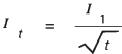
4. The short circuit current rating for copper conductors given in the table are values for 1
sec.and for other duration the current may be calculated by the following formular;
|
|
lt: Short circuit current fort second (A) |
|
l1: Short circuit current for 1 second (A) |
|
|
t: Short circuit duration(second ) |
5. The duration of short circuit based on these assumptions should be between 0.2 sec
and 5 sec
|
Conductor area |
Short circuit current for 1sec |
Conductor area |
Short circuit current for 1sec |
|
mm2 |
A |
mm2 |
A |
|
1.5 |
143 |
70 |
10016 |
NO.1, Jiangnan Cable has advanced production technology and equipment. From the manufacturing of conductors to the processing of insulation, shielding and sheathing, every step is precise and strict to ensure the high quality of medium voltage cables.
NO.2, the quality control is extremely strict. The company has established a perfect quality inspection system, from the selection of raw materials to the finished products leaving the factory, checking at every level. Each medium-voltage cable has to go through a number of strict tests to ensure that the products meet or even exceed the national standards.
NO.3, Jiangnan Cable has invested heavily in research and development. According to the market demand and customers' special requirements, we can develop medium voltage cables with different characteristics, such as better environmental resistance and better current carrying capacity. Moreover, the rich product line can meet the different needs of various complex projects and provide customers with one-stop cable solutions.
Our Cases
what we finished
| Customized | Cable Specifications | Insulation Material | Shield Construction | Sheath Material | Armor Structure | Special Performance | Length | ||||||||
| Conductor Cross Section | Number of cores | Material Type | Insulation Thickness | Shielding type | Number of Shielding Layers | Material Selection | Color Identification | Armor type | Armor Layers | Fire resistance | Waterproof performance | Flame retardant performance | Cold resistance | Sample customization request meters | |
|
√ |
√ | √ | √ | √ | √ | √ | √ | √ | √ | √ | √ | √ | √ | ||
Listed in Hong Kong in April 2012, Wuxi Jiangnan Cable Co., Ltd. is a National Key High and New Tech Enterprise specialized in production, sales and research on cables & wires. The company covers an area of more than 650,000 square meters with total assets of more than 8 billion Yuan. With more than 1,500 sets of domestic and foreign advanced production and testing equipment, we have passed many Management System Certifications.
Conductor resistance
|
Resistance communication formula |
R=P*L/A |
R: Resistance in ohm per phase |
|
p: Specific resistance,Ω.mm²/m |
||
|
A: Conductor area,mm² |
||
|
L: Conductor length,m |
||
|
Resistance as a Function of Temperature |
R=RO[1+a(t-20)] |
RO: Resistance at t=20℃ |
|
t: Conductor temperature,℃ |
||
|
α: 0.00393 for copper |
|
Conductor D.C.Resistance of Tinned Annealed Stranded Copper at 20℃ |
|||||
|
Conductor area |
Max.resistance at 20℃ |
Conguctor area |
Max.resistance at 20℃ |
||
|
Class2 |
Class5 |
Class2 |
Class5 |
||
|
mm² |
ohm/km |
mm² |
ohm/km |
||
|
0.5 |
36.7 |
40.1 |
70 |
0.270 |
0.277 |
|
0.75 |
24.8 |
26.7 |
95 |
0.195 |
0.210 |
|
|
18.2 |
20.0 |
120 |
0.154 |
0.164 |
|
1.5 |
12.2 |
13.7 |
150 |
0.126 |
0.132 |
|
2.5 |
7.56 |
8.21 |
185 |
0.100 |
0.108 |
|
4 |
4.70 |
5.09 |
240 |
0.0762 |
0.0817 |
|
6 |
3.11 |
3.39 |
300 |
0.0607 |
0.0654 |
|
10 |
1.84 |
1.95 |
|
|
|
|
16 |
1.16 |
1.24 |
|
|
|
|
25 |
0.734 |
0.795 |
|
|
|
|
35 |
0.529 |
0.565 |
|
|
|
|
50 |
0.39 |
0.393 |
|
|
|
Current reting for continous service
Current ratings for EPR and XLPE insulated power cable
Current rating of EPR and XLPE insulated power cable in continuous service at maximum rated
|
Conductor area |
1core |
2core |
384c0f6 |
|||
|
mm2 |
Amp |
Amp |
Amp |
|||
|
1 |
19 |
16 |
14 |
|||
|
1.5 |
23 |
20 |
16 |
|||
|
2.5 |
40 |
26 |
21 |
|||
|
4 |
51 |
34 |
28 |
|||
|
6 |
52 |
44 |
36 |
|||
|
10 |
72 |
61 |
50 |
|||
|
16 |
96 |
82 |
67 |
|||
|
25 |
127 |
108 |
89 |
|||
|
35 |
157 |
133 |
110 |
|||
|
50 |
196 |
167 |
137 |
|||
|
Conductor area |
1core |
2core |
384c0f6 |
|||
|
mm2 |
Amp |
Amp |
Amp |
|||
|
70 |
242 |
206 |
169 |
|||
|
95 |
293 |
249 |
205 |
|||
|
120 |
339 |
288 |
237 |
|||
|
50 |
389 |
331 |
272 |
|||
|
185 |
444 |
377 |
311 |
|||
|
240 |
522 |
444 |
365 |
|||
|
300 |
601 |
511 |
421 |
|||
|
|
d.c. |
a.c. |
d.c. |
a.c. |
d.c. |
a.c. |
|
400 |
690 |
670 |
587 |
570 |
483 |
469 |
|
500 |
780 |
720 |
663 |
612 |
546 |
504 |
|
630 |
890 |
780 |
757 |
663 |
623 |
546 |
* The tabled current ratings must be adjusted for ambient air temperatures other than45℃ by multpying the rating factors in the following table
|
Ambient temp.℃ |
35 |
40 |
45 |
50 |
55 |
60 |
65 |
70 |
75 |
80 |
|
Rating factors |
1.10 |
1.05 |
1.00 |
0.94 |
0.88 |
0.82 |
0.74 |
0.67 |
0.58 |
0.47 |
|
|
NO. |
1.0mm²Amp |
1.5mm²Amp |
2.5mm²Amp |
NO. |
1.0mm²Amp |
1.5mm²Amp |
2.5mm²Amp |
|
I1=Current rating for single cores |
5 |
12 |
14 |
19 |
16 |
7 |
9 |
13 |
|
7 |
9 |
13 |
17 |
19 |
7 |
9 |
12 |
|
|
N=Number of cores |
10 |
|
12 |
15 |
24 |
6 |
8 |
11 |
|
12 |
|
11 |
14 |
27 |
6 |
8 |
11 |
|
|
|
|
11 |
13 |
33 |
6 |
7 |
9 |
Installation Recommendation
1. Minimum Bending Radius: The minimum recommended installation bending radinus shall be in accordance with IEC60092-352 as following:
● Bending radii for cables rated up to 1.8/3kV
|
Cable construction |
Overall dia.of cable(D) |
Min.radius of bend |
|
|
Insulation |
Covering |
||
|
Thermoplastic or thermosetting with cicular copper conductors |
Unarmored or unbraided |
≤25mm |
4Da |
|
>25mm |
6D |
||
|
Metal braid screened or armored |
Any |
6D |
|
|
Metal wire armored,metal tape armored or metal-shaped |
Any |
6D |
|
|
Composite polyester/metal tape screened units or collective tape screen |
Any |
8D |
|
|
Thermoplastic or thermosetting with shaped copper conductors |
Any |
Any |
8D |
|
Mineral |
Hard metal sheathed |
Any |
6D |
|
6D for defined circuit integrity |
|||
● Bending radi for cables rated at 3.6/6 (7.2)kV and above
|
Cable Construction |
Overall diameter of cable (D) |
Min.radius of bend |
|
Single-core Cable |
Any |
12D |
|
Three-core Cable |
Any |
9D |
2. Pulling tension
The cable puling tension during installation can be estimated through the following formula:
● For armored cable
(P=50Nxtotal criss section area of conductors)
● For unarmored cable
(P=25N×total cross section area of conductors)
Additional tension will be supplied form the braid and the insulation and sheathing material